05/05/2014
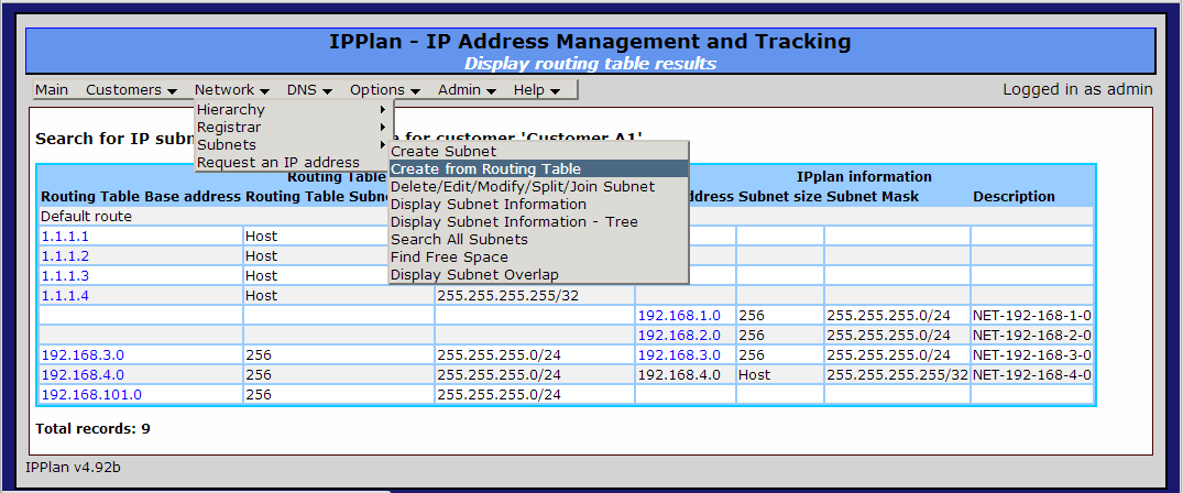
IPplan is an IP/DNS address management system designed for use by service providers. There are many methods and operating systems on which you can install it including but not limited to Ubuntu Server 14.04. One of the great features I find useful is the means to query routing tables via SNMP.

If you choose to install on Ubuntu 14.04 then the following may be of use to you. Please note this is not a how to guide and if your inclined then it may assist you in bypassing the few hours I spent twiddling with packages and permissions.
Base install of Ubuntu Server 14.04
INSTALL PACKAGES:
sudo apt-get update
sudo apt-get dist-upgrade
sudo apt-get install apache2
sudo apt-get install mysql-server
sudo apt-get install php5
sudo apt-get install php5-snmp
sudo apt-get install php5-mysql
GET IPPLAN AND EXTRACT:
cd /
sudo mkdir downloads
cd downloads
wget http://sourceforge.net/projects/iptrack/files/ipplan/Release%204.92/ipplan-4.92b.tar.gz
tar -xvzf ipplan-4.92b.tar.gz
sudo mv ipplan /var/www/ipplan
MYSQL INSTALL:
mysqladmin -u root -p create ipplan
mysql> grant all on ipplan.* to ipplan@localhost identified by ‘MYSQL PASSWORD’;
mysql>flush privileges;
mysql>exit
EDIT CONFIG.PHP:
sudo vi /var/www/ipplan/config.php
define(“DBF_TYPE”, ‘maxsql’);
define(“DBF_HOST”, ‘localhost’);
define(“DBF_USER”, ‘ipplan’);
define(“DBF_NAME”, ‘ipplan’);
define(“DBF_PASSWORD”, ‘IPPLAN PASSWORD’);
define(“ADMINUSER”, ‘admin’);
define(“ADMINPASSWD”, ‘IPPLAN PASSWORD’);
define(“ADMINREALM”, ‘admin’);
sudo chown -R /var/www/ipplan
sudo chmod -R 750 /var/www/ipplan
ACCESS WEB PORTAL:
http://ipplan_ip_address_here/ipplan/admin/install.php
# I updated my apache2 default directory
# May need to create some /tmp/dhcp /tmp/dns directories
 Leave a Comment » |
  Monitoring, Rancid, Routing |
  Permalink
 Posted by swampie51
02/04/2013
!
!
!
ip local pool IPADDR_VPN_POOL x.x.x.x x.x.x.x
!
aaa new-model
!
aaa authentication login LETMEIN_GROUPx local
aaa authentication login userauthen local
aaa authorization network LETMEIN_GROUPx local
!
username AVAYAx1 password 0 xxxx1
username AVAYAx2 password 0 xxxx2
username AVAYAx3 password 0 xxxx3
username AVAYAx4 password 0 xxxx4
!
crypto isakmp policy 1
encr 3des
hash md5
authentication pre-share
group 2
!
crypto isakmp client configuration group LETMEIN_GROUPx
key $x$x$
pool IPADDR_VPN_POOL
pfs
!
crypto ipsec transform-set MYTSET_3DESx esp-3des esp-md5-hmac
!
crypto ipsec security-association lifetime seconds 86400
!
crypto dynamic-map dynmap2 20
set transform-set MYTSET
set pfs group2
reverse-route
!
crypto map clientmap client authentication list userauthen
crypto map clientmap isakmp authorization list groupauthor
crypto map clientmap client configuration address respond
!
!
interface XXX/XXX
ip address X.X.X.X X.X.X.X
!
crypto map clientmap
crypto map clientmap 20 ipsec-isakmp dynamic dynmap2
!
Leave a Comment » | About Me, ACE, CCNP, CSM, DMVPN, Firewall, IP SLA, iPAD/iPhone, IPSEC, IUWNE, Layer2, Layer3, Linux, LYNC, Monitoring, Proxy, Rancid, Routing, SWITCH, Switching, Troubleshooting, VPN, Wireless | Permalink
Posted by swampie51
31/03/2013
The black and white from Cisco defines that the use of Data Rates options to specify the rates at which data can be transmitted between the access point and the client.
The data rates are available:
• 802.11a—6, 9, 12, 18, 24, 36, 48, and 54 Mbps
• 802.11b/g—1, 2, 5.5, 6, 9, 11, 12, 18, 24, 36, 48, or 54 Mbps
For each data rate, choose one of these options:
Mandatory—Clients must support this data rate in order to associate to an access point on the controller. Why force 11Mbps on an SSID, if not only to enforce better performance.
Supported—Any associated clients that support this data rate may communicate with the access point using that rate. However, the clients are not required to be able to use this rate in order to associate.
Disabled—The clients specify the data rates used for communication.
The notes say the clients must support and not operate at this rate and the supported option identifies a not required. I think I will attempt to test the overall enforcement and remove any ambiguity. I know this is one that I’ve always assumed what the options mean…
More to follow
Leave a Comment » | About Me, ACE, CCNP, CSM, DMVPN, Firewall, IP SLA, iPAD/iPhone, IPSEC, IUWNE, Layer2, Layer3, Linux, LYNC, Monitoring, Proxy, Rancid, Routing, SWITCH, Switching, Troubleshooting, VPN, Wireless | Permalink
Posted by swampie51
31/03/2013
The following link was one I found when investigating the use of 1131AG access points. The positioning on a ceiling is certainly better qualified after reviewing this document.
http://www.cisco.com/en/US/prod/collateral/wireless/ps7183/ps469/product_data_sheet09186a008008883b.html
Leave a Comment » | About Me, ACE, CCNP, CSM, DMVPN, Firewall, IP SLA, iPAD/iPhone, IPSEC, IUWNE, Layer2, Layer3, Linux, LYNC, Monitoring, Proxy, Rancid, Routing, SWITCH, Switching, Troubleshooting, Uncategorized, VPN, Wireless | Permalink
Posted by swampie51
24/02/2013
Update the 000-default file with the following details below to add basic authentication.
<VirtualHost *:80>
ServerAdmin webmaster@localhost
DocumentRoot /var/www
<Directory />
Options FollowSymLinks
AllowOverride None
order deny,allow
</Directory>
<Directory /var/www/>
Options Indexes FollowSymLinks MultiViews
AllowOverride none
order allow,deny
allow from all
</Directory>
ScriptAlias /cgi-bin/ /usr/lib/cgi-bin/
<Directory “/usr/lib/cgi-bin”>
AuthType Basic
AuthName “CVS REPO”
AuthUserFile /etc/apache2/.htpasswd
AllowOverride All
Require valid-user
</Directory>
The command below will allow you to create a new user and it will lead you through adding a password for that user.
network@S-ABD-RANCID:$ sudo htpasswd -c .htpasswd myuser
Leave a Comment » | About Me, ACE, CCNP, CSM, DMVPN, Firewall, IP SLA, iPAD/iPhone, IPSEC, IUWNE, Layer2, Layer3, Linux, LYNC, Monitoring, Proxy, Rancid, Routing, SWITCH, Switching, Troubleshooting, Uncategorized, VPN, Wireless | Permalink
Posted by swampie51
24/02/2013
To permit ANY packets that come from an IPsec tunnel without checking any ACLs such as the OUTIDE_ACCESS_IN The following example enables IPsec traffic through the ASA without checking ACLs:
hostname(config)# sysopt connection permit-vpn
Leave a Comment » | About Me, ACE, CCNP, CSM, DMVPN, Firewall, IP SLA, iPAD/iPhone, IPSEC, IUWNE, Layer2, Layer3, Linux, LYNC, Monitoring, Proxy, Rancid, Routing, SWITCH, Switching, Troubleshooting, Uncategorized, VPN, Wireless | Permalink
Posted by swampie51
24/02/2013
VLAN TRUNKING PROTOCOL is designed to ease administration of a large number of switches. It manages addistions, deletions and renaming. You can only apply one VTP domain to a switch.
There are 3 versions of VTP and only two of those are actively used (V3 is CAT/OS). VTP is a method of synchronising the vlan databases of switches. The term domain is used to identify a cluster/group of switches. If the databases are to be shared then the domain name and any passwords set must match (not totally true, read below for more details).
VTP advertisements are based upon the revision number and are sent when a change is made or every 5 minutes. The advertisments are multicast frames.
A summary advertisment is sent out every 300 seconds and if a change occurs.
A subset advertisment after a configuration change. VLAN name, SAID value, type and MTU.
A request from client switch used to obtain up to date information.
Each change made to a vlan will increase the revision number. A switch will compare revision numbers when it receives an advertisement. A switch will overwrite its VTP database if the update from one of it’s peers is higher (potentially making an automatic change to the assigned vlan’s). The advertisement is forwarded onto any neighbours. If the switch receives a VTP advertisement with a lower revision it will reply with it’s advertisement to update it’s neighbour.
The roles are:
SERVER: This is the default and will allow the switch to create, delete and rename vlan’s.
CLIENT: Apparently clients cannot make changes. However, I have seen events where client switches have been able to pass on updates to server peers.
TRANSPARENT: Allows the creation, deletion and renaming vlan’s but all information remains local. This mode will forward VTP information to its peers.
The use of show vtp status identifies the version in use, the revision number and the number of vlans that are being passed around via VTP.
Leave a Comment » | About Me, ACE, CCNP, CSM, DMVPN, Firewall, IP SLA, iPAD/iPhone, IPSEC, IUWNE, Layer2, Layer3, Linux, LYNC, Monitoring, Proxy, Rancid, Routing, SWITCH, Switching, Troubleshooting, Uncategorized, VPN, Wireless | Permalink
Posted by swampie51
24/02/2013
Q-in-Q allows already tagged frames across a network by tunnelling them inside a single vlan. The process adds a second 802.1Q tag to each frame. As the packets traverse the network the network the infrastructure see’s the outside tag and forwards based on that vlan. Q-in-Q tunnels are usually implemented by service providers to encapsulate a customers multiple vlans into a single vlan.
Eg: as a simple example
Customer vlans 1,2,3,4,5
Service provider vlan 100
Customer switch trunk vlans 1-5 —-> (service provider dot1q-tunnel vlan 100) ——> vlans 1-5
This is enabled with:
switchport mode dot1q-tunnel
The tunnel interfaces should be setup at either end of the overall link.
Leave a Comment » | About Me, ACE, CCNP, CSM, DMVPN, Firewall, IP SLA, iPAD/iPhone, IPSEC, IUWNE, Layer2, Layer3, Linux, LYNC, Monitoring, Proxy, Rancid, Routing, SWITCH, Switching, Troubleshooting, Uncategorized, VPN, Wireless | Permalink
Posted by swampie51
24/02/2013
ISL: Cisco proprietary and encapsulates the original frame in a 26 byte header and a 4 byte trailer. The ISL vlan’s are 1-1001.
802.1Q: Open standard and inserts a field in the 802.1P header, just after the source mac-address. The 802.1Q vlan’s are 0-4094.
If a mixture of ISL and 802.1Q is in use then the matching vlan’s can map across up to the ISL limit.
Points to note include if a non trunking port receives and ISL encapsulated frame then the frame is dropped. This is because the header and trailer cause the frame to exceed the MTU and may be counted as an error.
If an 802.1Q frame is received on a non trunking port then the source and destination mac-addresses are checked and the frame is switched normally at Layer2.
Leave a Comment » | About Me, ACE, CCNP, CSM, DMVPN, Firewall, IP SLA, iPAD/iPhone, IPSEC, IUWNE, Layer2, Layer3, Linux, LYNC, Monitoring, Proxy, Rancid, Routing, SWITCH, Switching, Troubleshooting, Uncategorized, VPN, Wireless | Permalink
Posted by swampie51
24/02/2013
DTP sends out adverisments every 30 seconds and ports can become a trunk either by configuration or dynamically. A port can be in one of five modes:
ACCESS: A user port in a single clan.
TRUNK: A port has negotiated its a trunk with its peer.
NON-NEGOTIATE: The port is a trunk and does not negotiate with any peers.
DYNAMIC DESIRABLE: Dynamically negotiates with its peer and will become a trunk if the other end is set to trunk,dynamic desirable or dynamic auto.
DYNAMIC AUTO: Passively waits to negotiate DTP with its peer. The peer must be configured as a trunk or dynamic desirable.
Leave a Comment » | About Me, ACE, CCNP, CSM, DMVPN, Firewall, IP SLA, iPAD/iPhone, IPSEC, IUWNE, Layer2, Layer3, Linux, LYNC, Monitoring, Proxy, Rancid, Routing, SWITCH, Switching, Troubleshooting, Uncategorized, VPN, Wireless | Permalink
Posted by swampie51
14/02/2013
The process of upgrading/downgrading the AP/LAP’s can be covered as with most networking in many ways. This method is one of my favourites and allows you to copy the code off of an existing LWAP node.
To copy off of an LWAP node:
archive upload-sw tftp:///c1130-rcvk9w8-mx.DEFAULT
Download IOS onto the device:
archive download-sw /force-reload /overwrite tftp:///c1130-rcvk9w8-mx.DEFAULT
Leave a Comment » | About Me, ACE, CCNP, CSM, DMVPN, Firewall, IP SLA, iPAD/iPhone, IPSEC, IUWNE, Layer2, Layer3, Linux, LYNC, Monitoring, Proxy, Rancid, Routing, SWITCH, Switching, Troubleshooting, Uncategorized, VPN, Wireless | Permalink
Posted by swampie51
27/01/2013

Amir Mohammed, Henning Speckels, Nigel Sims, Julian Shead, Alastair Read, Paul Stayt, Jonathan Myers, Aaron Milton-Eldridge, Peter Massey.
Leave a Comment » | About Me, ACE, CCNP, CSM, DMVPN, Firewall, IP SLA, iPAD/iPhone, IPSEC, IUWNE, Layer2, Layer3, Linux, LYNC, Monitoring, Proxy, Rancid, Routing, SWITCH, Switching, Troubleshooting, Uncategorized, VPN, Wireless | Tagged: Oxfordshire County Council - Jan 2013 - Network Team | Permalink
Posted by swampie51
03/01/2013
Follow these steps to reset the password that allows the Admin user access to the ACE module:
Connect to the console port of the ACE module in the Catalyst 6500 series switch.
Reboot the ACE module from the Catalyst 6500 series CLI.
“no power enable module x”
“power enable module x”
During the bootup process, Press ESC when the “Waiting for 3 seconds to enter setup mode…” message appears on the terminal (see the example below). If you miss the time window, wait for the ACE module to properly complete booting, reboot the ACE module from the Catalyst 6500 series CLI, and try again to access the setup mode by pressing ESC. The setup mode prompts if you want to reset the admin password. Enter y. The “Resetting admin password to factory default” message appears. The ACE module deletes the admin user password configuration from the startup configuration and resets the password back to the factory default value of admin.
<<abridged>>
Starting lcpfw process…
inserting IPCP klm
Warning: loading /itasca/klm/klm_session.klm will taint the kernel: no license
See http://www.tux.org/lkml/#export-tainted for information about tainted modules
Module klm_session.klm loaded, with warnings
inserting cpu_util klm
create dev node as ‘mknod /dev/cpu_util c 236 0’
getting cpu_util dev major num
making new cpu_util dev node
Session Agent waiting for packets .
Waiting for 3 seconds to enter setup mode…
Entering setup sequence…
Reset Admin password [y/n] (default: n): y
Resetting admin password to factory default…
XR Serial driver version 1.0 (2004-11-08) with no serial options enabled
<<abridged>>
Loading.. Please wait…Done!!!
The boot process continues as normal and you are able to enter the admin password at the login prompt.
Leave a Comment » | About Me, ACE, CCNP, CSM, DMVPN, Firewall, IP SLA, iPAD/iPhone, IPSEC, IUWNE, Layer2, Layer3, Linux, LYNC, Monitoring, Proxy, Rancid, Routing, SWITCH, Switching, Troubleshooting, Uncategorized, VPN, Wireless | Permalink
Posted by swampie51
29/12/2012
export http_proxy=http://:port
Leave a Comment » | About Me, ACE, CCNP, CSM, DMVPN, Firewall, IP SLA, iPAD/iPhone, IPSEC, IUWNE, Layer2, Layer3, Linux, LYNC, Monitoring, Proxy, Rancid, Routing, SWITCH, Switching, Troubleshooting, Uncategorized, VPN, Wireless | Permalink
Posted by swampie51
29/12/2012
!
interface Vlan100
ip address 172.16.255.254 255.255.0.0
ip helper-address 172.16.255.250
ip pim sparse-mode
ip policy route-map ROUTE-PROXY-TRAFFIC-POLICY
!
!
access-list 101 permit tcp 172.16.1.0 0.0.0.255 any eq www
access-list 101 permit tcp 172.16.1.0 0.0.0.255 any eq 443
!
!
access-list 102 permit ip 172.16.1.0 0.0.0.255 any eq 50
access-list 102 permit ip 172.16.1.0 0.0.0.255 any eq 51
access-list 102 permit udp 172.16.1.0 0.0.0.255 any eq 500
access-list 102 permit udp 172.16.1.0 0.0.0.255 any eq 4500
!
!
!
route-map ROUTE-PROXY-TRAFFIC-POLICY permit 10
match ip address 102
set ip next-hop 172.16.255.253
!
route-map ROUTE-PROXY-TRAFFIC-POLICY permit 50
match ip address 101
set ip next-hop 172.16.255.252
Leave a Comment » | About Me, ACE, CCNP, CSM, DMVPN, Firewall, IP SLA, iPAD/iPhone, IPSEC, IUWNE, Layer2, Layer3, Linux, LYNC, Monitoring, Proxy, Rancid, Routing, SWITCH, Switching, Troubleshooting, Uncategorized, VPN, Wireless | Permalink
Posted by swampie51
29/12/2012
If you actively use visio and are fed-up of the auto-connect as much as I was.. this is for you!
Enable or disable AutoConnect in all drawings
- On the Tools menu, click Options.
- Click the General tab.
- Under Drawing window options, select the Enable AutoConnect check box.
Leave a Comment » | About Me, ACE, CCNP, CSM, DMVPN, Firewall, IP SLA, iPAD/iPhone, IPSEC, IUWNE, Layer2, Layer3, Linux, LYNC, Monitoring, Proxy, Rancid, Routing, SWITCH, Switching, Troubleshooting, Uncategorized, VPN, Wireless | Permalink
Posted by swampie51
29/12/2012
A banner should be an informational warning/notification and not be a welcome to my device. I love a good banner and ascii, makes it all the more fun.
banner motd #
_~_
. / ^ -\ .
|\| (o) (o) |/|
|—–.OOOo–U–oOOO.——————|
| |
| * Authorised Access Only * |
| |
|_______________Oooo.__________________|
.oooO ( )
( ) ) /
\ ( (_/
\_)
This host is: $(hostname)
#
!
Leave a Comment » | About Me, ACE, CCNP, CSM, DMVPN, Firewall, IP SLA, iPAD/iPhone, IPSEC, IUWNE, Layer2, Layer3, Linux, LYNC, Monitoring, Proxy, Rancid, Routing, SWITCH, Switching, Troubleshooting, Uncategorized, VPN, Wireless | Permalink
Posted by swampie51
11/12/2012
Having the need to look at a converged network/telephony strategy with Microsoft LYNC and a request (not requirement) for users to be able to access the LYNC telephony over a Cisco wireless solution. Thinking a little out of the box I had got to the point of considering how to run ATM over a lightweight solution.
Along came AVC.. it certainly looks like a great step forward and I cant wait to have an opportunity to plau.
http://www.youtube.com/watch?feature=player_detailpage&v=h6ZLSc_lYEg
http://www.cisco.com/en/US/solutions/collateral/ns1015/ns483/ns780/at_a_glance_c45-649117.pdf
Leave a Comment » | About Me, ACE, CCNP, CSM, DMVPN, Firewall, IP SLA, iPAD/iPhone, IPSEC, IUWNE, Layer2, Layer3, Linux, LYNC, Monitoring, Proxy, Rancid, Routing, SWITCH, Switching, Troubleshooting, Uncategorized, VPN, Wireless | Permalink
Posted by swampie51
09/12/2012
I was looking at applying some filters to the ASDM logging viewer the other day and spent 5 minutes adding one of each type just to see what would be seen within the configuration. Its pretty straight forward and very similar to Wireshark filters. Nb. the use of a “;” where multiple filters are applied.
ASA Firewall Filters:
# Only source IP: FILTER:srcIP=172.16.0.50
# Only port 21: FILTER:srcPort=21;
# Source IP and port 21: FILTER:srcIP=172.16.0.50;FILTER:srcPort=21;
# Destination IP: FILTER:dstIP=10.206.164.41;
# Severity Level (4=WARNINGS): FILTER:sev=4;
Leave a Comment » | About Me, ACE, CCNP, CSM, DMVPN, Firewall, IP SLA, iPAD/iPhone, IPSEC, IUWNE, Layer2, Layer3, Linux, LYNC, Monitoring, Proxy, Rancid, Routing, SWITCH, Switching, Troubleshooting, Uncategorized, VPN, Wireless | Permalink
Posted by swampie51
02/12/2012
One of my earlier posts covered routing Netflow Exports to a server over IPSEC. The previous covered method relied on the use of GRE tunnels and loopback interfaces to forward the export to a central router which in-turn then forwarded them onto the collector.
The question of why bother and just not use a Cisco ASA to terminate the VPN could be raised and I guess the requirements and the methods of the outgoing connectivity will have input. However, the ASA will support the exporting of Netflow over and IPSEC tunnel and adding no funky workarounds. The two key things to remember are:
Add the collector to your INSIDE interface
Ensure the collector is covered by Interesting traff
Leave a Comment » | About Me, ACE, CCNP, CSM, DMVPN, Firewall, IP SLA, iPAD/iPhone, IPSEC, IUWNE, Layer2, Layer3, Linux, LYNC, Monitoring, Proxy, Rancid, Routing, SWITCH, Switching, Troubleshooting, Uncategorized, VPN, Wireless | Permalink
Posted by swampie51
21/11/2012
Rancid has always been one of my favourite network management tools along with Cacti, SolarWinds, Kiwi Cat tools, ManagEngine Netflow and Cisco ACS. I’ve always known that Rancid has some extra features under the hood to allow for occasional and or bulk changes. After having a spare 30 minutes whilst also attempting to keep myself occupied…
Kiwi is out of the window. !!!
After digging around the world library (Google), I came across a script a guy had compiled which in its simplest form reads a text file for a list of devices eg;
192.168.3.1
192.168.3.2
192.168.3.3
The script then reads a text file for a list of required commands eg;
configure terminal
snmp-server chassis-ID AWESOME-SWITCH
exit
wr me
exit
When the script is run you are prompted to locate the input file identified by the script from a defined directory. After keying in the file name and issuing ENTER, the script prompts again for the text file from a defined directory. Again, keying in the file name and issuing ENTER. At this point the script reads the changes and prints them to the console asking if you wish to proceed and asking you to type “yes” (no speech marks) ENTER. Anything more or less than “yes” and the script bombs out. However, “yes” being the all powerful keyword, allows the script to continue allowing the Rancid server to login to each device listed and applying the changes listed. As an additional feature it also outputs all of the session output into a log file with a date/time stamp. My next task will be looking at adding the logs to CVS to simplify the audit process.
The folder structure that I created to make this work for me as identified in the script below was:
USER@LINUX-SVR:/var/lib/rancid/network-change-scripts$
Create a file in this directory with your changes as would be inputted on a command line e.g:
conf t
hostname rancid-changed-me
exit
wr me
exit
USER@LINUX-SVR:/var/lib/rancid/network-change-devices$
Create a file in this directory with your list of hosts e.g:
1.1.1.1
2.2.2.2
3.3.3.3
USER@LINUX-SVR:/var/lib/rancid/network-change-logs$
The script will generate logs dynamically when the script is called.
The script looks something like this if the file is called push-config.sh:
USER@LINUX-SVR:/var/lib/rancid/network-change-scripts$ cat push-config.sh
!– Begin config-push.sh —
#!/usr/local/bin/bash
#
# The purpose of this script is to automate configuration changes to a
# large number of devices. The script identifies the device list, as well
# as the change script, and then pushes the changes one by one.
# When the script runs you will be prompted through through the process,
CLOGINPATH=”/usr/lib/rancid/bin/clogin”
CREDENTIALS=”/var/lib/rancid/.cloginrc”
DEVICELISTPATH=”/var/lib/rancid/network-change-devices/”
CHANGESCRIPTPATH=”/var/lib/rancid/network-change-scripts/”
CHANGELOG=”/var/lib/rancid/network-change-logs/changelog-`date +%T-%d-%m-%Y`.log”
clear
echo “=====[ Rancid Config Push Script ]=====”
echo “”
echo “Please enter the proposed device list:”
echo “`ls $DEVICELISTPATH`”
echo “————————————–”
echo -n “> ”
read DEVICELIST
if [ -f $DEVICELISTPATH$DEVICELIST ]
then
echo “”
echo “Device List = \”./device-lists/$DEVICELIST\” (confirmed)”
else
echo “”
echo “Device list = \”./device-lists/$DEVICELIST\” (does not exist!)”
echo “Aborting…”
echo “”
exit
fi
echo “”
echo “Please enter name of change script:”
echo “`ls $CHANGESCRIPTPATH | grep -v “.sh” | grep -v “device-lists”`”
echo “———————————–”
echo -n “> ”
read CHANGESCRIPT
if [ -f $CHANGESCRIPTPATH$CHANGESCRIPT ]
then
echo “”
echo “Change Script = \”./change-scripts/$CHANGESCRIPT\” (confirmed)”
echo “”
else
echo “Device list = \”./change-scripts/$CHANGESCRIPT\” (does not exist!)”
echo “Aborting…”
echo “”
exit
fi
echo “– Proposed Changes –”
echo “`cat $CHANGESCRIPTPATH$CHANGESCRIPT`”
echo “– Proposed Changes –”
echo “”
echo “Are you sure you want to proceed? If so, type \”yes\”:”
echo -n “> ”
read AREYOUSURE
if [ $AREYOUSURE != “yes” ]
then
echo “”
echo “Aborting…”
echo “”
exit
else
echo “”
echo “Implementing Changes…”
echo “”
fi
#for i in `cat $DEVICELISTPATH$DEVICELIST`
# do echo “===[ $i ]===”
# $CLOGINPATH -f $CREDENTIALS -x $CHANGESCRIPTPATH$CHANGESCRIPT $i
#done
for DEVICE in `cat $DEVICELISTPATH$DEVICELIST`
do
echo “===[ $DEVICE ]===”
echo “” >> $CHANGELOG
echo “===[ $DEVICE ]===” >> $CHANGELOG
echo “” >> $CHANGELOG
OUTPUT=`$CLOGINPATH -f $CREDENTIALS -x $CHANGESCRIPTPATH$CHANGESCRIPT $DEVICE`
echo “$OUTPUT” >> $CHANGELOG
done
# — end config-push.sh —
To run the script from a command line in the same directory use ./config-push.sh
Leave a Comment » | Linux, Monitoring, Rancid | Permalink
Posted by swampie51
05/12/2011
This was a new feature that came in with the later IOS versions where you can use KRON a’la CRON to run tasks on a scheduled basis. In smaller environments it negates the need for things such as Solarwinds NCM and or RANCID.
Define the Kron policy
# kron policy-list Backup
# cli show run | redirect tftp://<TFTP Server IP>/2801/config
Define the Kron Occurrence
# Kron occurrence Backup at 17:00 Wed recurring
# policy-list Backup
Leave a Comment » | Monitoring, Rancid | Permalink
Posted by swampie51
05/12/2011
7)
Using the CVS Web Interface we can enhance Rancid with a pretty neat interface. To do this we need to edit with vi: /etc/cvsweb/cvsweb.conf go to line 59 to make a few changes. Here is an example from the configuration file. You will need to change the second row to match your group name (BACKUPS line) and point this to where rancid store the CVS. After that is completed you need to save the file (:wq!).
~~~~~~~~~~~~~~~~~~~~~~~~~~~~~~~~~~~~~~~~~~~~~~~~~~#
@CVSrepositories = (
‘local’ => [‘Local Repository’, ‘/var/lib/cvs’],
‘BACKUPS’ => [‘AUTOMATED BACKUPS’,’/var/lib/rancid/CVS’]
);
~~~~~~~~~~~~~~~~~~~~~~~~~~~~~~~~~~~~~~~~~~~~~~~~~~#
In addition to the above change to secure the main CVSROOT you should also select the 1 variable on the hide CVSROOT option in the same file. At this point there is the option to tidy up the HTML to suit your purpose. The next step is to get the CVS icons etc into the /var/www folder we create a symbolic link for it.
o #sudo ln -s /usr/share/cvsweb /var/www/cvsweb
After that you should be able to access your Rancid-CVS on
http://”IP of the Rancid Machine”/cgi-bin/cvsweb/
8)
We only then need to create a simple cron job to run rancid-run frequently such as every day or 12 hours depending on the size of your network or requirements
o #crontab -e -u rancid
run ranid-run script every day at 00:30 and removed the old logs the first day of every month at 00:15
~~~~~~~~~~~~~~~~~~~~~~~~~~~~~~~~~~~~~~~~~~~~~~~~~~#
30 00 * * * /home/rancid/bin/rancid-run
~~~~~~~~~~~~~~~~~~~~~~~~~~~~~~~~~~~~~~~~~~~~~~~~~~#
The crontab command will update the /var/spool/cron/crontabs/rancid file.
9)
Finally to ensure that all packages are upto date at the point of install issue the following commands.
o #sudo apt-get update
o #sudo apt-get upgrade
Leave a Comment » | Linux, Monitoring, Rancid | Permalink
Posted by swampie51
05/12/2011
This is a brain dump of the RANCID install process that I’ve put together and fully tested using Ubuntu 11.04
Requirements:
o Ubuntu-Server 11.04 “ubuntu-11.04-server-i386.iso”
o username: notwork
o password: notworking
Notes:
_________________________________________________________________________________________________________________________________________
text preceeded by # is a command to be issued
text enclosed in a box ~~~~~~~~~~~# is the editing of a file
I personally use vi to edit text/config files remembering that “ESC” then “:wq!” will save the file (write,quit and force) and “i” will allow you to insert text.
_________________________________________________________________________________________________________________________________________
1)
Use apt-get to install the programs
Install Ubuntu following a standard build and at package selection only choose ssh server. Once the build has completed login as user notwork with a password of notworking (change username/password as you see fit). Once logged int the console enter the following:
o #sudo apt-get install apache2
o #sudo apt-get install expect
o #sudo apt-get install cvs
o #sudo apt-get install cvsweb
o #sudo apt-get install checkinstall
o #sudo apt-get install rancid-core rancid-util build-essential
This will have installed Rancid in /etc/rancid.
2)
We need to configure the /etc/rancid/rancid.conf file to create groups of devices. At least one group needs to be configured and adding multiple groups means that the names must be separated with a space. The example below will create the groups where all the device configurations will be stored:
~~~~~~~~~~~~~~~~~~~~~~~~~~~~~~~~~~~~~~~~~~~#
LIST_OF_GROUPS=”switches”
~~~~~~~~~~~~~~~~~~~~~~~~~~~~~~~~~~~~~~~~~~~#
3)
The next step is to setup the CVS configuration with the following command:
o #sudo su -c /var/lib/rancid/bin/rancid-cvs -s /bin/bash -l rancid
There should be a new folder added in the /var/lib/rancid directory, this has been named after the group(s) you created earlier in 2). Navigate into this folder and open up the router.db with vi. Here you will specify what router/switches you want to add to your CVS. For example:
~~~~~~~~~~~~~~~~~~~~~~~~~~~~~~~~~~~~~~~~~~~#
192.168.0.25:cisco:up
procurve.foo.org:hp:up
192.168.0.35:juniper:down
~~~~~~~~~~~~~~~~~~~~~~~~~~~~~~~~~~~~~~~~~~~#
4)
After this has been completed we then need to tell rancid how to access the devices. This is done by creating a .cloginrc script file in the /var/lib/rancid folder with the following commands:
#sudo touch .cloginrc
#sudo vi .cloginrc
Use the following example which will attempt to telnet to all devices with a username of user and a password of password. This file can be updated to meet many of your standard requirements or use multiple methods for varying examples.
add method * telnet
add user * user
add password * password
5)
We need to secure the .cloginrc file by changing the owner and file permission.
#sudo chown rancid:rancid /var/lib/rancid/.cloginrc
#sudo chmod 640 /var/lib/rancid/.cloginrc
6)
Lastly we should be done and should see if rancid is working correctly by running the process as the rancid user with the following command
#sudo -u rancid -H /usr/bin/rancid-run
You can check if the command was successful by checking the logs in /var/log/rancid/switches. It should say in the log message “All routers successfully completed.”.
See the Stage 2 post to install/configure the CVS web interface and Stage 2.5 to use rancid to update device configurations either in bulk or singularly.
Leave a Comment » | Linux, Monitoring, Rancid | Permalink
Posted by swampie51
05/12/2011
One for Mr Grumpy…
In the likely event that you upgrade a FWSM or possibly some other similar hardware. It seems that during the upgrade process it kills your SSH configuration and you need to regenerate the keys. This can be achieved with a simple “crypto key generate rsa”. However, if you run a linux management system then you may need to delete and reset the key on the linux host for the remote node your attempting to access..
sudo ssh-keygen -f “/var/lib/<user>/.ssh/known_hosts” -R <ip-address>
where <user> is the user such as root on the local linux host and <ip-address> is the address of the host your connecting to. An example to remove the key from the local user is:
ssh-keygen -f “/home/network/.ssh/known_hosts” -R 1.1.1.1
Leave a Comment » | Linux, Monitoring, Rancid | Permalink
Posted by swampie51
05/12/2011
Say What! “really awesome new Cisco confIg differ”
http://www.shrubbery.net/rancid/
RANCID is one of those things that once you have it up and running you wonder how you ever survived without it. In years of implementation and management of network infrastructure the means to easily identify adhoc changes that magically occur are every network engineers nightmare. Mix in a little bit of TACACS+ and you have an ideal solution for offering accountability and management of your infrastructure. The great thing that RANCID does is to chuck the output of numerous commands into a sub-version process and highlights the changes which occur. So, I’ve put together a step by step process of installing RANCID onto a certain Linux distribution, as well as dropping some brain dump elements and some tit-bits identifed by Mr Grumpy …

Leave a Comment » | Linux, Monitoring, Rancid | Permalink
Posted by swampie51